-
On Mars:
Exploration of the Red Planet. 1958-1978
-
-
-
- WORKING TOWARD JULY
1975
-
-
-
- [192] Money problems would always haunt
the Viking project. The scarcity of dollars especially affected
the development of the lander and its science payload and
repeatedly tried people's patience and equanimity. Early in 1973,
Joseph R. Goudy, the Langley Viking Project Office resident
engineer at JPL, commented on budget cuts that led to the
dismissal of about 200 employees at the California laboratory on
rather short notice:
-
- These cutbacks have created a different
atmosphere and environment, resulting in a change in attitude. Six
months ago, when the [Viking Project Office] came in with a new
requirement or direction that required additional or premature
effort, it was generally accepted with the attitude. "We don't
think it's necessary but it's their money; if they want it, we'll
do it." Now, with the Orbiter having to take rather severe cuts,
this is no longer considered "their" money and the attitude has
become much more critical. if not down-right hostile.
66
-
- Henry Norris, looking for ways to keep his
orbiter personnel from reacting too negatively to the repeated
budget cuts, tried to convince them-and for the most part he
succeeded-that the budget was just one of the many realities that
a good engineer or manager had to live with and work around as he
tried to do his job.
-
- The tasks assigned to the orbiter teams
were laid before them in a five-year schedule, which ended with a
pair of mid-summer 1975 launches. The master plan was presented
for the first time at the Viking Project Management Council
meeting in February 1970, and it reflected the changes brought by
the stretchout.
-
- The pace of the work at JPL assumed a
rhythm familiar to the people who had worked on other NASA
projects. The determining factors, "drivers"....
-
|
Table 33 [193]
|
|
Viking Orbiter
Schedules
|
|
|
|
Event
|
Proposed before
|
Proposed after
|
Actual
|
|
1 Jan. 1970
|
1 Jan. 1970
|
Dates
|
|
|
|
Preliminary design review
|
May 1970
|
Jan. 1972
|
19-20 0ct. 1971
|
|
Critical design review
|
June 1971
|
Jan. 1973
|
9-lO July 1973
|
|
Start proof-test spacecraft
test
|
Aug. 1972
|
March 1974
|
Jan. 1974
|
|
Qualification test completed
|
Nov. 1972
|
July 1974
|
Jan. 1975
|
|
Shipment of first flight hardware to
KSC
|
Feb. 1973
|
Dec. 1974
|
Feb. 1975
|
|
Launch
|
July 1973
|
July 1975
|
20 Aug. 1975
|
|
|
|
|
9 Sept. 1975
|
SOURCE: Information on the 1970 master plan
was awaken from Henry Norris, "Viking Orbiter Project Staff Meeting-
Minutes of January 13 and 14, 1970," memo, 19 Jan. 1970.
-
-
- ....in NASA parlance, for the designers
and engineers were master schedules that determined when major
hardware components had to be completed so the launch dates could
be met. But the realities of designing and building the spacecraft
did not always conform to calendar milestones, and the variance
led to frequent revisions of the schedules. At every step along
the way, the work was formally documented in a large number of
Viking project documents. By cross-checking and coordinating these
documents, the project manager at Langley could be assured that
the orbiter, lander, science payloads, launch vehicles, ground
support equipment, flight control facilities, and the tracking
system would all function as required when the hardware was
brought together and assembled for the launch and flight to Mars.
This system of mass documentation, formal reviews, telecons, and
informal conversations worked because the people associated with
the effort believed in delegated management. Jim Martin's
centralized responsibility and authority for Viking was a key
factor to the project's success, but equally important was the
esprit de corps among the Viking teams at the working level.
67
-
- The troops at JPL functioned within
divisions responsible for specific engineering activities or
disciplines. Norris and his orbiter staff allocated funds,
prepared plans and schedules, assigned tasks, and received
progress reports, but the divisions carried out the actual design
and development of the spacecraft and experiment hardware, as well
as prepared and operated such facilities as the Deep Space Network
and the Space Flight Operations [194] Facility. Each division
chief and his subordinates not only supervised their personnel but
also selected the engineers who represented their divisions on the
orbiter team.*
68
-
- The structure of management at JPL did not
fit Jim Martin's management scheme. The people at Langley had
always worked through a more centralized organization, in which
everyone was directly responsible to the project director, and the
Viking Project Office was uneasy with the JPL system. Martin knew
that the organizational structure of the lab would not likely be
changed just for this mission, so he went to Pasadena in the early
spring of 1970 to observe firsthand how JPL worked. Specifically,
he wanted to know: How had JPL dealt with hardware problems in the
past? How did it plan to manage the Viking orbiter in the future?
How would it control the flight phase of a mission?
69
-
- Henry Norris believed that the time Martin
spent with division managers and Viking representatives at JPL led
him to understand more clearly the lab's approach to project
management. Martin was still "not entirely comfortable" with the
organization, Norris reported, but at least the project director
had been exposed to it and the men who filled the ranks. Likewise,
the people at JPL began to appreciate the sources of Martin's
concerns and continued to work with the project office to improve
and strengthen JPL management control over the teams in Pasadena.
70
-
- Although they had adopted different
approaches, the personnel at Langley and JPL were working toward
the same goal. Once the baseline orbiter configuration had been
established in February 1969, the next major orbiter goal was the
preliminary design review (PDR). This formal review, held on 19-20
October 1971, came at the end of the conceptual phase for the
design of the orbiter systems; the specialists were now ready to
work on the detailed design of the hardware. Once the basic
soundness of all aspects of the orbiter was approved, the teams
would head for the next important milestone, the critical design
review (CDR). Getting to the PDR had been a major accomplishment.
made difficult by the repeated problems with the budget; but the
teams at JPL had completed their design work and coordinated their
efforts, attending weekly meetings and frequently using the
telephone along the way. In fact. more than 60 meetings were held
that directly impinged upon the design of the orbiter.
-
- The preliminary design review gave all
interested parties a look at the orbiter as JPL planned to build
it. Once the conceptual design was complete, work on the design of
breadboards, or first working test models, of the basic orbiter
subsystems would begin. These designs would be evaluated at
subsystem PDRs an once approved, work on e breadboards would [195]
proceed, with their suitability for conversion into flight
hardware being confirmed during a series of subsystem critical
design reviews. A general A general CDR for the entire Viking
orbiter system would certify the readiness of the orbiter staff to
go to the next step-building the flight-ready orbiters.
-
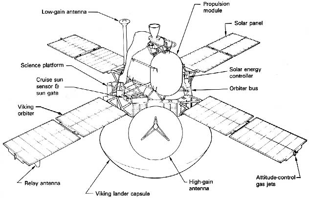
- By October 1971, the orbiter had assumed
the basic configuration it would have when launched in 1975. The
spacecraft had grown considerably larger than its Mariner Mars 71
predecessor. Most noticeable visually were the larger solar panels
and the larger high-gain antenna. But all the internal subsystems
were taking on a Viking identity of their own as well. The Mariner
inheritance was still there, but instead of directly transferring
subsystems from one craft to another, the engineers were borrowing
from Mariner experience and know-how. Still, it was this transfer
of technological knowledge from Mariner Mars 71 and Mariner Venus
73 that permitted the Viking orbiter personnel to get the craft
ready to fly on time with a minimum of problems and money
crises.
-
- Jack Van Ness, deputy Viking project
manager, recorded in his "Viking Weekly Highlights Report" that
the orbiter system preliminary design review was well organized
and informative. Only 22 action items remained for solution. "This
relatively small number is somewhat indicative of the clarity and
thoroughness of the presentations." At the conclusion of the
review, the Viking Advisory Review Panel and the Orbiter System
Manager's Advisory Panel provided a favorable overall evaluation
of the orbiter status. None of the evaluations turned up any
critical problems that would give Martin's Viking Project Office
cause for concern. 71
-
- With the PDR behind them, Norris's people
began to prepare the detailed designs of the 21 orbiter
subsystems. Soliciting requests for proposals from industrial
contractors, selecting companies to build the subsystems, and
negotiating contracts occupied the months from October 1971 to
July 1972. One contract was not let until July 1973. Meanwhile,
the various divisions at JPL bad begun to work on the subsystems
that would be built at the laboratory. Preliminary design reviews
for these subsystems began in January 1972 and lasted until late
November.
-
- Close on the heels of the PDRs came the
subsystem critical design reviews, which spanned January to July
1973. When the subsystem CDRs were completed, a general CDR at JPL
9-10 July 1973 evaluated the entire orbiter system as it had
evolved to date. The CDR panel, the Viking Advisory Panel, and the
Orbiter System Manager's Advisory Panel all expressed their
confidence in JPL's performance and the quality of the teams'
work. 72 The technical problems being encountered by the
orbiter were the routine kind that appeared during the course of
most spacecraft projects-recurring difficulties with poor-quality
integrated circuits and an unhappy experience when an early
production propulsion tank ruptured because of a metallurgical
failure.
-
- During the summer of 1973, only two
subsystems caused genuine concern. The infrared thermal mapping
(IRTM) subsystem was behind [196] schedule, but by mid-July the
Santa Barbara Research Center had the trouble under control, and
the subsystem CDR was held that month. The data-storage-subsystem
tape recorder's failure to operate at a satisfactory speed put it
on the Viking Project Office's "Top Ten Problems" list. In October
the "54L" integrated circuits were also added to the list.
Overall, however, the orbiter was shaping up as a well-behaved
spacecraft, and everyone was pleased. Concern over the orbiter's
financial problems was constant, but the project management was
confident that Henry Norris's teams were on schedule and doing
well. By drawing on Mariner heritage, they had the Viking orbiter
under control. 73
-
- In mid-1973, the orbiter hardware entered
the test phase. The first test, called the modal test, was
conducted with the orbiter development test model, to determine if
the mathematical model used for the engineering load analysis was
correct. The modal test ran from late May until the end of July. A
week later, General Electric delivered the first computer command
subsystem. In late August, the propulsion-system engineering test
model was test-fired at the NASA Edwards Test Station in
California, while at JPL the flight-data-subsystem breadboard was
checked out with other pieces of hardware that were to be linked
to it, such as the visual imaging subsystem, the IRTM, and the
atmospheric water detector. During the first and second week of
September, other tests were run to determine the effect of shock
on various orbiter instruments. Joseph Goudy reported to Martin on
the 14th that the results from the pyrotechnic shock tests were
much better than they had anticipated: "None of the subsystems
that were on board for the tests appeared to have suffered any
adverse effects�." The sensitive instruments would not be harmed
when the spacecraft was explosively separated from the Centaur
launch vehicle stage and the lander was explosively separated from
the orbiter. 74 In mid-December 1973, JPL completed the vibration
stack test of the orbiter and lander development test models.
Since this was the first time that orbiter and lander hardware had
been mated and tested together, everyone in Pasadena was
particularly satisfied when no important questions were raised by
the examinations. 75
-
- With the new year upon them, the orbiter
team focused its attention on final assembly of the proof-test
orbiter and tests of this first flight-style hardware. These
qualification tests would determine the spaceflight worthiness of
the orbiter system designs as they had been rendered into
hardware. The assembly process took three months as each of the
subsystems was checked out and assembled onto the orbiter bus.
During April and May, the engineers at JPL conducted the system
readiness test, verifying the functioning of all orbiter
components. The successful examination of the orbiter hardware
prompted Goody to report to the Viking management at Langley that
they were on schedule and that the assembly of the proof-test
orbiter had served as a "pathfinder" for the fabrication of the
flight orbiters. 76 In the process of building this first craft,
officially designated Viking orbiter 1 (VO-l), the spacecraft
assembly personnel members at JPL learned some....
|
Table 34 [whole
page 197]
|
|
Growth in Capacity of Data
Storage Subsystems
|
|
|
|
|
Mariner 64
|
Mariner 69
|
Mariner 71
|
Viking 75
|
|
|
|
Number of tape
recorders
|
1
|
1
|
1
|
2
|
|
Number of tracks
|
-
|
4
|
8
|
8 x 2
|
|
Recording rate
|
-
|
16 200 bits per sec
|
132 000 bits per sec
|
301 172 bits per sec, tracks1 through
7; 4 and 16 kilobits per sec, track 8
|
|
Playback rate
|
81/3 bits per sec
|
270 bits per sec
|
1, 2, 4, 8, or 16 kilobits
|
1, 2, 4, 8, or 16 kilobits
|
|
Storage capacity
|
5.4 million bits
|
23 million bits
|
180 million bits
|
640 million bits x 2
|
|
Length of tape
|
100 meters
|
111 meters
|
168 meters
|
384 meters x 2
|
|
Weight
|
-
|
19 kg
|
11 kg
|
7.7 kg x 2
|
|
Contractor
|
-
|
Lockheed Electronics Co. Inc.,
Plainfield, N.J.
|
Lockheed Electronics
|
Lockheed Electronics
|
NOTE: The data subsystems (reel-to-reel tape
recorders) used on the Mariner and Viking spacecraft permitted
recording scientific data and sobsequently playing it back through
the communications subsystem for transmission to Earth. As the number
of experiments increased and the amount of data to be stored and
played back grew, successive data storage systems became more
complex. Each new tape recorder had greater capacity, posing new
technological challenges. In Viking, each data subsystem rape
recorder weighed 3.3 kg less than the Mariner 71 data subsystem
recorder, while having 3.6 times the information storage
capacity.That accomplishment took time and caused some real headaches
for the Viking managers, but the completed recorders worked very
successfully during the missions.
-
- [198]....important lessons that would help
them build Viking orbiter 2 and 3, the orbiters that would fly to
Mars. One problem they encountered was the lack of sufficient work
stands, particularly during the installation of the thermal
insulating blanket. More stands were ordered, to avoid any
bottleneck during the assembly of the flight articles. The
proof-test orbiter was moved on 8 May from the Spacecraft Assembly
Facility to the Environmental Laboratory, where it would go
through the rigors of vibration, electromagnetic interference,
pyrotechnic, thermal vacuum, and compatibility tests during the
summer of 1974. At the same time, engineers would begin assembling
and testing VO-2 and VO-3. 77
-
- On schedule with satisfactory results, the
VO-1 tests were completed in late August. As the JPL team turned
its attention to readying VO-3 for early examination, however,
unexpected budget problems brought a change in plans.
78 On 27 September, the orbiter staff was forced to
order all testing of the third orbiter to cease. The second test
team was disbanded; no money was available for testing. VO-3 was
put into storage, and the proof-test orbiter (VO-1) was
redesignated a flight unit. VO-1 and VO-2 would be the....
-
-
-
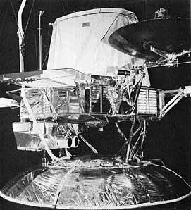
- The thermal-control model of the Viking
orbiter mated to the lander thermal-effects simulator was used in
August 1973 to verify the effects solar radiation would have on
the spacecraft. The science platform with imaging system and other
instruments is attached under the orbiter.
-
-
|
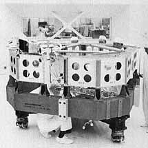
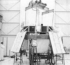
[199] Building the Viking
Orbiter at Jet Propulsion Laboratory in 1974. Men working
inside the chassis, right, fabricate the orbiter bus
structure. Below right, they attach the propulsion module
to the propellant tanks. Below, solar panels are in place
on the nearly completed orbiter.
|
|
|
|
|
-
-
- [200]....spacecraft sent to Mars. To
ensure the acceptability of the proof-test hardware for flight, a
series of meetings were held during the next several weeks.
79 But an orbiter design qualification review
scheduled for early October 1974 lost much of its significance,
since the change in plans had thrown off JPL's timing. As one
participant observed, it was hard for a review panel "to determine
if the Orbiter met all of its requirements in spite of all the
testing that has been done." 80
-
- After several more months of work, orbiter
VO-1 was verified for flight on 9 January 1975, and the VO-2 tests
were completed on the 31st. The orbiters were shipped to the
Kennedy Space Center in February, where a series of preflight
checks would be made through the spring and summer.
81 The Viking orbiter, remarkably close to early
weight predictions (see table 35), was a very carefully tested
piece of equipment. For the teams at JPL, the design, development,
fabrication, and assembly had, for the most part, gone according
to plan, schedule, and budget.
-
|
Table 35
|
|
Viking Orbiter
Specifications, 1969-1975
|
|
|
|
Orbiter Element
|
Baseline Orbiter
|
PDR Orbiter
|
Flight Orbiter
|
|
Feb. 1969
|
Oct. 1971
|
Feb. 1975
|
|
|
|
Bus dimensions:
|
|
|
|
|
- Long sides
|
-
|
-
|
139.7 cm
|
|
- Short sides
|
-
|
-
|
50.8 cm
|
|
- Height
|
45.7 cm
|
45.7 cm
|
45.7 cm
|
|
|
|
Distance from launch vehicle
attachment points to lander attachment points
|
-
|
3.29 m
|
3.29 m
|
|
|
|
Distance across extended solar
panels, tip to tip
|
7.80m
|
9.75 m
|
9.75 m
|
|
|
|
Weight with fuel
|
2298.6 kg
|
2304.3 kg
|
2324.7 kg
|
|
|
|
Weight of fuel
|
1862 kg
|
1404.8 kg
|
1422.9 kg
|
|
|
|
Weight of science instruments
|
57.6 kg
|
65.4 kg
|
65.2 kg
|
|
- Visual imaging system
|
21.8 kg
|
42.05 kg
|
40.05 kg
|
|
- Infrared thermal mapper
|
13.6 kg
|
7.48 kg
|
9.30 kg
|
|
- Mars atmospheric water
detector
|
-
|
15.90 kg
|
15.90 kg
|
SOURCE: JPL "Viking Project Orbiter System,
Visual Presentation, February 13, 14, 1969''[Feb.1969]; JPL "Viking
73 Project Orbiter System PDR, October 19-20,1971, Presentation
Material ' [Oct.1971]; and Martin Marietta Aerospace, Public
Relations Dept., The Viking Mission to Mars (Denver, 1975).
pp.III-25,III-27,III-32,III-33.
-
-
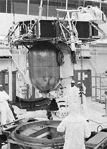
- [201] Configuration of the mated Viking orbiter and
capsule in cruise mode.
-
-
-
- [201] Carl D. Newby, supervisor of the
Spacecraft Development/Mechanical Support Group, oversaw the
assembly of the orbiters. It was the biggest spacecraft Newby and
his team had built, and because it was so big it was an easy craft
on which to work-they had room to move around during the assembly
process. Newby pointed out that it requires a special personality
to work on space hardware and a special dedication. Fabricators
come to view the spacecraft as part of their lives, to care about
it. Working in a closed environment, they have to learn to live
with one another, as well. Spacecraft builders must be adaptable,
very careful, and thoughtful. One false move, one thoughtless
motion can destroy an assembly or component worth thousands of
dollars or months of time. Damage to a spacecraft usually also
requires requalification of the injured components or perhaps
requalification of the entire craft. Workers on the Viking
orbiters-many had worked on Ranger most had worked on the
Mariners-were very fond of their spacecraft.As Newby repeatedly
reminded the specialists at JPL, the orbiter was a "good
spacecraft to work on, it was on time and on budget."
82 Building the Viking landers, however, was a
completely different story.
-
-
* Divisions and their representatives assisting the
Viking orbiter staff at JPL, spring 1970: Quality Assurance and
Reliability, G.E. Nichols; Project Engineering, V.R. Galleher;
Data Systems, G.F. Squibb; Space Science, M.T. Goldfine;
Telecommunications, J.R. Kolden; Guidance and Control, A.E.
Cherniack; Engineering Mechanics, W.J. Carley; Astrionics, J.D.
Acord; Environmental Sciences Simulation, N.R. Morgan; Propulsion,
W.J. Schatz; Mission Analysis, P.K. Eckman; and Technical
Information and Documentation, S.B. Hench.
-
-


