USSR Venus Orbiters
Courtesy of NASA's National Space Science Data Center
Venera 15 Launch Date: 1983-06-02
Venera 16 Launch Date: 1983-06-07
Description
 Venera 15 and Venera 16 were a two-spacecraft mission designed to use
8-centimeter (3-inch) band,
side-looking radar mappers to study the
surface properties of Venus.
Venera 15 was launched on June 2, 1983, and
Venera 16 on June 7. The two spacecraft were inserted into Venus orbit a
day apart with their orbital planes shifted by an angle of approximately
4° relative to one another. This made it possible to reimage an area
if necessary.
Venera 15 and Venera 16 were a two-spacecraft mission designed to use
8-centimeter (3-inch) band,
side-looking radar mappers to study the
surface properties of Venus.
Venera 15 was launched on June 2, 1983, and
Venera 16 on June 7. The two spacecraft were inserted into Venus orbit a
day apart with their orbital planes shifted by an angle of approximately
4° relative to one another. This made it possible to reimage an area
if necessary.
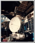
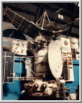
The two spacecraft were identical and were based on modifications to the orbiter portions of the Venera 9 and 14 probes. Each spacecraft consisted of a synthetic aperture radar (SAR) and a radio altimeter. Each spacecraft was in a nearly polar orbit with a periapsis at 62°N latitude. Together, the two spacecraft imaged the area from the north pole down to about 30°N latitude over the 8 months of mapping operations. In June 1984, Venus was at superior conjunction and passed behind the Sun as seen from Earth. No transmissions were possible, so the orbit of Venera 16 was rotated back 20° at this time to map the areas missed during this period.
Synthetic Aperture Radar
The Venera 15 and 16 synthetic aperture radar (SAR) systems were identical, and were used to map the surface of Venus at a resolution of 1 to 2 kilometers (.6 to 1.2 miles) over a period of 8 months. Radar is necessary for Venus surface mapping because the planet is covered by an unbroken layer of thick clouds. The radar was side-looking (at an angle of 10°) and operated at a wavelength band of 8 centimeters. The radar system consisted of a 6-meter (20-foot) diameter by 1.4-meter (4.6-foot) parabolic dish antenna connected to a transmitter, including a master oscillator and phase modulator, and a receiver linked to electronics and a buffer memory. The receiver and transmitter were run and coordinated by an on-board computer. All the components of the SAR except for the dish antenna were shared by the radio altimeter. The system would cycle between the SAR antenna and the radio altimeter antenna every 0.3 seconds.In SAR mode, the antenna would transmit a code sequence of 127 pulses, each of duration 1.54 microseconds. After transmission, the antenna was switched to the receiver, which recorded the reflection of the radar pulses from the surface over a period of 3.9 msec. After on-board processing with a digital automatic gain control system, the results were stored in a memory buffer until the radar picture was completed. Each radar picture (one per orbit) covered a strip of surface about 120 kilometers (75 miles) in width and 7,500 kilometers (4,660 miles) in length and took about 16 minutes of mapping. The data were then transferred to the on-board digital data storage unit for later transmission to Earth. The amplitudes of the reflected signals were processed on Earth to correct for atmospheric, geometric, and orbital effects and give images representing the slope, roughness, and emissivity of the surface of Venus.
The Venera spacecraft were in 24-hour polar orbits about Venus, with an apsis of 1,000 kilometers (62 miles) above the north pole. The radar mapping would typically begin at a latitude of 80° on the approach side of the pole and continue over the pole down to a latitude of 30° N. During the orbit, Venus would rotate on its axis by 1.5°, so the next mapping run would partially overlap the last. Mapping continued through one complete rotation of Venus, and covered 115 million square kilometers (44 million miles), about 25 percent of the surface of Venus.
Radio Altimeter
The Venera 15 and 16 radar (radio) altimeter systems were identical, and were used to determine the topography of the surface of Venus from the north pole down to about 30°N latitude. The altimeter was directed vertically downward and operated at a wavelength band of 8 centimeters (3 inches). The radar altimeter system consisted of a 1-meter (3-foot) diameter parabolic dish antenna connected to a transmitter, including a master oscillator and phase modulator, and a receiver linked to electronics and a buffer memory. The receiver and transmitter were run and coordinated by an on-board computer. All the components of the altimeter except for the dish antenna were shared by the synthetic aperture radar (SAR) mapper. The system would cycle between the altimeter antenna and the SAR antenna every 0.3 seconds.In altimeter mode, the antenna would transmit a code sequence of 31 pulses, each of duration 1.54 microseconds. After transmission, the antenna was switched to the receiver, which recorded the reflection of the radar pulses from the surface over a period of 0.67 msec. After on-board processing the results were stored in a memory buffer until the orbit was completed. The data were then transferred to the on-board digital data storage unit for later transmission to Earth. The data were processed on Earth to correct for atmospheric, geometric, and orbital effects and give altitudes of the Venus surface.
The altimetry would typically begin at a latitude of 80° on the approach side of the pole and continue over the pole down to a latitude of 30°N. Altimetry measurements were made every 2.5 kilometers (1.5 miles) along the flight path, and had a vertical resolution of 230 meters (755 feet). During the orbit, Venus would rotate on its axis by 1.5°, so the next altimetry run would partially overlap the last. Measurements continued through one complete rotation of Venus, and covered 115 million square kilometers (44 million miles), about 25% of the surface.