|
COMETS EARTH JUPITER KUIPER BELT MARS MERCURY METEORITES NEPTUNE OORT CLOUD PLUTO SATURN SOLAR SYSTEM SPACE SUN URANUS VENUS ORDER PRINTS
PHOTO CATEGORIES SCIENCEVIEWS AMERICAN INDIAN AMPHIBIANS BIRDS BUGS FINE ART FOSSILS THE ISLANDS HISTORICAL PHOTOS MAMMALS OTHER PARKS PLANTS RELIGIOUS REPTILES SCIENCEVIEWS PRINTS
|
Related Document
Download Options
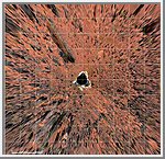
Planimetric (overhead view) map of the landing site, to a distance of 20 meters from the spacecraft. North is at the top in this and Plates 3-5. To produce this map, images were geometrically projected onto an assumed mean surface representing the ground. Features above the ground plane (primarily rocks) therefore appear displaced radially outward; the amount of distortion increases systematically with distance. The upper surfaces of the lander and rover also appear enlarged and displaced because of their height. Primary grid (white) is based on the Landing Site Cartographic (LSC) coordinate system, defined with X eastward, Y north, and Z up, and origin located at the mean ground surface immediately beneath the deployed position of the IMP camera gimbal center. Secondary ticks (cyan) are based on the Mars local level (LL) frame, which has X north, Y east, Z down, with origin in the center of the lander baseplate. Rover positions (including APXS measurements) are commonly reported in the LL frame. Yellow grid shows polar coordinates based on the LSC system. Cartographic image processing by U.S. Geological Survey. NOTE: original caption as published in Science Magazine, Volume 278, Number 5344, 5 December 1997, 'Mars Pathfinder Foldout' (Plate 2). |
