|
|
[13] Even though the fundamental characteristics of the camera were specified in the initial contractual agreement between ITEK and Martin Marietta, some elements of the design proved either impractical or undesirable. We were continually contemplating changes.
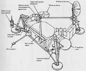
In the first drawings submitted by Martin Marietta a single camera was shown on the Lander. It was mounted on top of an extendable vertical mast (fig. 7). In this way the field of view could be varied and stereoscopic pairs of pictures could be obtained. However, it was an unusual stereoscopic perspective, as if one of our eyes was situated directly above the other. A more compelling objection involved redundancy and reliability. Did we really want to send a one-eyed traveler to Mars? The issue was never debated at any length. Even without any supporting arguments from the scientists the project managers quickly decided in favor of two cameras.
The next issue had to do with the mounting of cameras. There were several contradictory requirements. On the one hand, we wished to have an unobstructed view of the surface and to see the distant terrain. This dictated placement of the cameras on high masts. An even more dramatic solution, briefly considered, was the installation of three cameras, one at each of the triangular corners of the Lander body. On the other hand was the requirement to conserve space and weight. A high mast added undesirable weight and, in addition, was a protuberance that could not be accommodated in the small volume be tween the protective covers that encapsulated the Lander in transit to Mars.
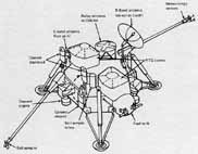
A compromise design was pursued for the better part of a year. The cameras would be mounted on hinged masts (fig. 8). During the trip to Mars they would be folded down; after landing they would be swung up, rotating through 180°. In retrospect it is difficult to see how this design concept survived for as long as it did. It introduced undesirable complexity and serious risk. During landing the sensitive camera electronics would be situated close to the base of the spacecraft, susceptible to collision with a boulder. If the swing mechanism failed to operate the cameras would remain in an inoperative position. If dust coated the exposed upper plate and base of the two mast sections, the deployed camera might be slightly tilted, introducing an unknown error in topographic analysis. Finally, if the cameras were not securely connected to the body of the spacecraft, they would not benefit from heat conducted from radioisotope energy sources. Isolated on the top of articulated masts, they might freeze to death. When all the liabilities were spelled out, the swing-up masts were discarded.
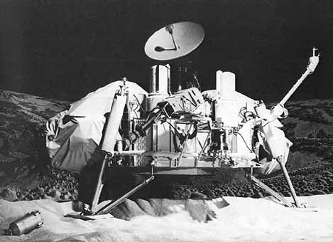
The solution was to mount two cameras on short stubby masts. (See figs. 9 to 11.) Although this fulfilled weight and thermal requirements, it dismayed the scientists. A third of the field of view below the horizon would be blocked by the Viking Lander. Especially severe was obscuration of the near field where we had our only opportunity to photograph the surface with high spatial resolution.
During a series of meetings the precise height of the masts above the surface was negotiated, the scientists reluctantly inching down and the engineers just as reluctantly moving up. We finally agreed on a goal of 1.5m. Having recently given ground on several other changes in camera design, the scientists were skeptical. Sure enough, the final height was 1.3m.
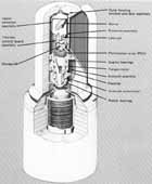
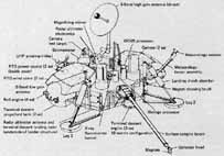
[14] Not everything worked to our disadvantage. Capitalizing on the conservative engineering practices utilized in the initial camera design, we were able to incorporate three additional spectral channels, something like having access to three different levels of infrared film in addition to color film for a conventional camera. As previously noted, the camera accommodated an array of twelve photosensors. Some sensors were mounted at slightly different focal positions. to permit maximum sharpness at various distances. Initial analyses indicated that four focus settings were required for the 0.04° high-resolution images and that two focus settings might be required for 0.12° color images. On this basis an array of twelve sensors was specified: one for black-and-white 0.12° survey, four for black-and-white 0.04° high-resolution, six for 0.12° color, and one extra-a bonus for a symmetrical design that called for two rows of six sensors (fig. 11).
Detailed testing with prototype electronics demonstrated something we had suspected. For the large-aperture sensors one focus setting was adequate. Nothing was to be gained by placing two sets of "color" diodes at two focus positions. This left three sensors unallocated. We quickly resurrected a former request to use three filters in the near infrared, a spectral region in which we anticipated instructive absorption effects in the martian sediment and rocks. Project managers graciously acceded to our request. In fact, it was deemed less expensive to continue with the original twelve-diode array than to redesign a smaller eight-diode array.
Someone suggested that we use the twelfth diode, the one included primarily for symmetry, for calibration with the Sun as a light source. By simply eliminating the amplifier associated with the diode, the electrical signal was reduced to a point where the Sun could be viewed directly without saturation of the electronics. Throughout camera construction the so-called Sun diode was incorporated but ignored. Nobody wanted to defend its use, but neither did it seem worthwhile to argue for its exclusion. Only when we reached Mars was the true usefulness of the Sun diode revealed. With unsuspectedly large amounts of dust suspended in the martian atmosphere, the apparent brightness of the Sun was an important measure of the atmospheric opacity.
Some design changes arose from our concern about hazardous conditions on Mars. Though space missions appear to rely on dispassionately objective numerical calculations, subjective appraisals continue to influence the design. Before Apollo there had been concerns that the astronauts would be trapped in quicksands of dust. The same worries were resurrected for Viking. More persuasive were calculations made by Carl Sagan regarding the erosive power of wind-driven sand. His arguments were based on telescopic observations of dust storms on Mars. Given the very low atmospheric density, less than a hundredth that of Earth, the wind velocities were clearly very high, on the order of 50 to 100m/sec. Theory and experiment suggested tha erosion rates under those conditions are very great, as much as one cm/yr. A twofold danger existed: first, that the spacecraft might be buried under a blanket of sand; second, that it might be sandblasted into oblivion. The horror stories were spiced by knowledge that two Soviet unmanned spacecraft...
[16] ....had mysteriously stopped operating just as they touched down on the surface of Mars, one in 1971 and a second in 1974.
Our first concern was to protect the glass window through which the light passed on its way to the nodding mirror. The window was slightly recessed, but otherwise susceptible both to coating and pitting by dust.
Like many apparently straightforward problems, this one proved intractable -but not for lack of entertaining suggestions. A variety of mechanical brushes and wipers were proposed but rejected because of their mechanical complexity. Someone even suggested, half facetiously, that we mount a weather vane atop the camera, so that the recessed window pointed downwind when not in use. The protective strategy finally endorsed was adequate, even if lacking in elegance. Not fully believing in any one approach, we decided that safety lay in numbers. First, the window was coated with special material that resisted dust deposition and erosion. In addition, a second transparent window was installed in front of the primary window. On command, the second window could be swung out of the way. When not in use, the camera slewed to a position where the recessed window was protected behind a fixed post. During a final attack of anxiety when the cameras were almost completely built, we strapped on a device which would blow a jet of compressed air (actually carbon dioxide) against the window, thereby sweeping away any thin veneer of dust.
Other potential problems were unevenly pursued. A report that dust might adhere electrostatically stimulated a high-priority test program, but, somewhere along the line, enthusiasm for yet another protective device to dispel surface charges dissipated. Enough is enough.
Turning our attention to other parts of the camera, we belatedly worried about the possibility of wind-driven dust seeping in and jamming moving parts. In particular, there was an external lip on the housing adjacent to the bearings that facilitated the rotational movement of the upper camera section. Could dust settling on the external lip sift through several protective seals into the bearing assembly? There was only one way to convince the fearful. One of the cameras was set up in a special wind tunnel maintained by the McDonnell-Douglas Company in St. Louis. Fine-grained rock powder was introduced, creating an awesome dust storm. Fine dust clung to every surface, but the bearings remained dustfree. Only when the test continued to a point where the cameras were virtually buried did performance deteriorate. Not unexpectedly, that was due to dust caked between the protective post and the upper housing.