


|
|
[6] Inevitably there is something haphazard about the initial stages of planning a complicated space probe. It is easy to talk in general terms about the scientific questions to be asked, even to list the general types of instruments to be employed. But a spacecraft is not made up of generalities. It is composed of millions of parts, each manufactured with specified characteristics to carry out a particular function.
How is the gap bridged between generality and specificity? In this instance, it is accomplished by the writing of a document that describes in engineering terms exactly what the scientist- customers wish. This document is then circulated among private industry. Any company that wishes to compete for the business makes a bid.
Note that the camera is described in "engineering" rather than "scientific" terms. There is an underlying tension separating the two. Take one of the more obvious camera characteristics, spatial resolution. The scientific goal is to take pictures of the sharpest clarity, showing the smallest detail. But you can't very well ask the manufacturer to give you a "best" picture. Instead we elected to specify that the resolution should be 0.04°. This is sometimes termed the camera's instantaneous field of view. The concept is best illustrated by looking at an enlargement of a Viking picture (fig. 2). With high magnification the image is seen to comprise a regular checkerboard of spots, each with a particular shade of gray. Each space on the checkerboard approximates a circle which subtends 0.04° as viewed from the camera position. A single trace of 360°...
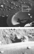
[7] ...includes 9000 checkerboard squares. A 60° swath in elevation includes 1500. A large panorama, 60° by 360°, comprises the impressively large array of 131/z million checkerboard squares, or pixels (picture elements).
How did we decide to specify a resolution of 0.04°? The issue was debated at numerous meetings where we were challenged to demonstrate quantitatively the increase in scientific return with increase in resolution. At one point, we were presented with two pictures of different resolution and asked to identify the one with the better resolution. The presenter was trying to develop the argument that, because we couldn't differentiate between the two, it made no difference what the actual camera resolution was. Predictably the argument collapsed when everyone correctly identified the two pictures. In the final analysis, the selected resolution of 0.04° was an educated guess of the best that was instrumentally possible.
Over the course of several years, one of our team members, Fred Huck, already had analyzed extensively the design tradeoffs between performance capability and engineering complexity. He had a thorough familiarity with engineering practicalities. It was he who sat down with Glenn Taylor, and, in a matter of a few days, conjured up the majority of detailed manufacturing specifications. Jumping ahead in our story, it is interesting to note that after nearly two Earth years of operation on the surface of Mars the cameras are still performing according to their original specifications.
Certain camera characteristics were dictated by spacecraft constraints. Notable among these were weight, power, and bit rate. The first two are obvious, but the third deserves some comment. Cameras generate a great deal of information in a very short time. This implies some mechanism for storing all that information. In a conventional camera the film is that storage device. In a television camera system the data is generally stored on magnetic tape. When the Viking mission was conceived, it was known that the entire spacecraft would have to be sterilized to avoid the possibility of carrying any Earth organisms to Mars. The procedure adopted was heat sterilization. Just before launch the entire spacecraft would be placed in an oven, and heated to 110°C for approximately 40 hours. It was feared that neither film nor magnetic recording tape would be stable at that temperature, and that surface chemicals would volatilize. What was needed was a camera that required no onboard storage device, but generated data precisely at the rate that it was being transmitted to Earth. Two transmission rates of 16000 and 250 bits per sec were available, so these same rates were selected for camera operation also.
In the spring of 1970 we met to review the six proposals for camera construction submitted by private industry. Strictly speaking the decision was not ours. The Martin Marietta Company had already been selected to assemble the entire Lander. It was their task to identify subcontractors to build the various science instruments. Their choices were subject to approval by NASA managers at Langley Research Center and Washington Headquarters. Our own team acted as a science lobby. Working outside the contractual framework, we attempted to persuade those who had to make the choices. Unfamiliar as we were with the intricacies of business arrangements, we sometimes cynically assumed that our advice would be ignored. Our concern was unfounded. As the project unfolded, our views were solicited at every point of decision. Indeed, many times our judgments were requested on subjects where our understanding was more scantily intuitive than solidly reasoned. Although flattered, I was frequently embarrassed by the willingness of managers to adopt our suggestions, while tactfully disregarding our general ignorance of spacecraft construction and operation.
As we considered the six camera proposals, one clearly ranked above the others. The technical section was crisply written. It was obvious that the proposing company, using their own funds, had made detailed preliminary calculations. The proposed camera design was elegant, avoiding failure-prone mechanically moving parts and gears in favor of electronic components. There was only one problem. The price tag was much higher than that of the low bidder. Not only that, some competing companies could point to considerable experience, much of it with NASA endorsement, in the development of cameras for planetary spacecraft. Although the Viking Project was in its infancy, concerns about escalating costs had already surfaced. We presented our case with little optimism, and were amazed when the decision was announced. The cameras would be built by the company we favored, the ITEK Corporation of Lexington, Mass.
The ITEK-built instrument is called a facsimile camera. The name is inherited from a technique in telegraphy whereby a picture is divided into a grid of small squares. The brightness of each square is converted into an electrical signal. A sequence of signals sent over the telegraph wire serves as a blueprint for registering the equivalent array of squares on photographic film at the receiving end. In this way, a "facsimile" of the original picture is produced.
In the ITEK design this general concept was refined to produce an instrument with amazing accuracy and versatility. An essential feature is that the pixels are acquired in relatively slow sequence, thereby meeting the requirement for operation without tape recorder support. It differs from a conventional camera in that at no time is a complete image [8] recorded in the focal plane. Instead of film, there is a tiny photosensor fitted with a mask permitting it to view a solid angle of 0.04° in the object scene. For low-resolution, color, and infrared sensors the view angle is three times larger, 0.12°.
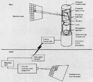
A simplified view of the camera configuration is shown in figure 3. Light from the scene is reflected from a mirror, nodding back and forth around a horizontal axis. Focused through a lens system, it is recorded on a photosensor in the focal plane. Each time the mirror nods, light from successive points along a single apparent vertical line in the object scene is recorded by the photosensor. When this cycle is completed, the entire upper assembly of the camera moves a small amount around an azimuth rotation axis so that an adjacent vertical line is scanned. As more and more vertical lines are recorded the picture builds in the azimuthal or "horizontal" dimension, moving from left to right, and, given enough time, providing a continuous panorama up to 342.5°.
An alternate way of conceiving camera operation is to imagine you could miniaturize yourself and peer through the small pinhole in the focal plane that is the photosensor aperture. All that you would see would be a flickering light. Each change in light level would document a transition between a bright and dark region in a vertical line.
In a superficial sense the operation of the camera is remarkably simple. As it goes about its business you can watch the slotted window in front of the mirror slowly move in a clockwise arc. You can detect a regular sparkle of light as the mirror looks back at you. You can listen to the whir of the mirror, and a solid thunk as the upper housing turns in azimuth five times every second.
In fact, the camera is a complex device, involving extraordinary accuracy, reliability, and miniaturization. Several examples illustrate the point. Each pixel must be accurately positioned with relation to other pixels not only in the same vertical line, but also in adjacent lines. To assure this result the velocity of the mirror must be precisely controlled. The margin of error, the maximum allowable difference between the desired and actual positions of the upper edge of the mirror is only 0.01 mm, or one- tenth the diameter of a human hair. This accuracy has to be maintained at 512 positions as the mirror rotates through a maximum of 30° and then swings back to its starting position every fifth of a second. Vertical line-scan and azimuth-stepping servocontrol electronics compensate for a slight but significant off-axis position of sensors in the focal plane.
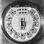
The camera employs an array of twelve photosensors (photodiodes), any one of which can be used to acquire a picture. Some of the diodes are mounted at different focal positions to achieve optimum focus at various distances. Others are equipped with filters. Measurement of "blue," "green," and "red" light permits construction of color images. Each line is scanned successively with each of three photodiodes to record the relative contributions of blue, green, and red light. Then the adjacent line is scanned three times. For color pictures the pixel size is 0.12° instead of 0.04°. The increase...
[9] ...in size, with related loss of spatial resolution, is required because relatively less light passes through the filter.
The photosensor array represents a difficult problem in miniaturization. The aperture over each high-resolution (0.04°) diode is 0.041 mm in diameter. Even though so small as to be barely detectable with the unaided eye, the size of the aperture must be carefully controlled, within several thousandths of a millimeter. The entire assembly, including twelve diodes and associated preamplifiers is only 3.4 cm in diameter and 2 cm high (fig. 4).
In conventional cameras exposure times are controlled by varying the lens aperture or time of exposure. In the Viking Lander camera varying exposures are attained by sampling the electrical signal in different ways. Sixty-four different signal levels, corresponding to 63 gray levels, are measured. The camera can be commanded to operate at any of six gain levels. At one extreme, the 63 sampling points are spread out across the entire dynamic range of the camera, the sort of strategy one would utilize for a scene with very high contrast and high light levels. At the other extreme, the 63 gray levels are clustered over a small fraction of the dynamic range, providing good discrimination in a scene with low light levels or low contrast. Thirty-two offsets also permit one to raise the light level corresponding to the lowest gray level without changing the increment of intensity between successive gray levels. This would be a useful adjustment in situations where contrast is low but general light level is high, and, therefore, ...
[10] ...no signals are being recorded at the lower end of the dynamic range.
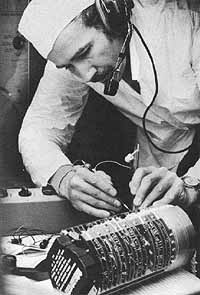
All these operations- diode selection, sampling rates, and video signal processing- are controlled by complex electronic circuits in the lower camera assembly. As the camera design evolved, more and more circuits were crowded on the mounting boards, resulting in an impressive electronic labyrinth.
|
Height |
55.6 cm |
|
Diameter | |
|
14.4 cm |
|
25.6 cm |
|
Weight |
7.26 kg |
|
Power | |
|
34 W |
|
27 W |
|
Environmental operating conditions | |
|
Earth or CO2 |
| |
|
1000 mbar |
|
Vacuum |
|
2.8 to 20 mbar |
| |
|
+113°C |
|
-126 to + 52°C |
|
up to 70 m/sec dust storm |
|
Characteristics |
|
|
|
|
- | |||
|
Instantaneous field of view, deg |
0.12 |
0.12 |
0.04 |
|
Frame width, deg. | |||
|
61.44 |
61.44 |
20.48 |
|
2.5; 352.5 |
2.5; 342.5 |
2.5; 342.5 |
|
- | |||
|
Field of view, deg | |||
|
| ||
|
| ||
|
- | |||
|
Geometric depth of field, m |
1.7 to infinity |
1.7 to infinity |
1.7 to infinity |
|
In focus distance, m |
3.7 |
3.7 |
1.9, 2.7, 4.5, and 13.3 |
|
Picture elements per line |
512 |
512 |
512 |
|
Bits per picture element |
6 |
6 |
6 |
|
Bits per degree azimuth |
2.84 x 10⁴ |
8.53 x 10⁴ |
8.53 x 10⁴ |
|
Time per degree azimuth | |||
|
1.84 |
5.52 |
5.52 |
|
2.0 |
6.0 |
6.0 |