|
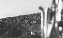
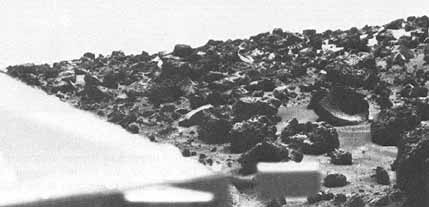
[94-95] As was the
case for Lander 1, some of the more fascinating Lander 2
pictures are those taken looking back across the spacecraft.
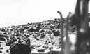
Figures 107 and 108 show an early morning and midday view of
the same region. The pipes at the right were connected to
the Orbiter during the trip to Mars in order to stabilize
and monitor the internal Lander environment. The top of leg
1, at the rear of the triangular spacecraft, occurs in the
bottom center.
Although most of the blocks on the
surface are irregularly broken and pitted, some have smooth,
conchoidal fractures.
An example appears at the far left in
figure 108. This morphology is typical for glassy to fine
grained volcanic rocks.
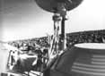
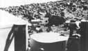
Figure 109 is a low resolution view
showing a larger area than that contained in the high
resolution views of figures 107 and 108. A large number of
spacecraft components are identifiable, including the RTG
protective covers, two of three reference test targets for
the cameras, and the dish shaped S band antenna.
Brightness contouring in the sky,
particularly well developed in figure 109 but detectable in
many other pictures, is caused by increasing sky brightness
as the camera moves toward the Sun. The Lander camera
transforms this continuous gradation into a series of
discrete steps with increasing brightness. The filamentous
horizontal bright streaks in the sky are caused by spurious
reflections of light from the outer camera housing. When the
camera mirror is at certain critical positions, this light
interferes with the normal radiance of the scene.
|