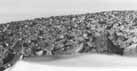
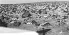
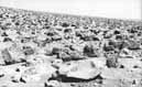
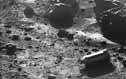
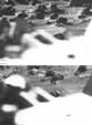
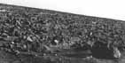
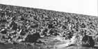
Home Table of Contents What's New Image Index Copyright ScienceViews Search


SP-425 The Martian Landscape


A Rocky Plain


Figure 83

Figure 84

Figure 85


[80-81] Two views of the same rock strewn plain are shown. Figures 83 and 84 were taken in the early morning. The Lander faces approximately northeast. With lighting from the east the S band antenna, mounted on the rear of the spacecraft, casts a shadow on the ground to the left of the Lander. Figure 85 was taken at noon.

The many boulders seem to stand apart from the bland background, as if they were carefully positioned on some giant Hollywood set. This appearance probably is due to erosion by wind- eolian deflation, in geological parlance-that has carried away finegrained material between larger rocks. Some of the boulders actually stand on pedestals of protected fine grained substrate.


Figure 86

Figure 87

Figure 88

Figure 89


[83-84] Figures 86 and 87 are two views of the same area in front of the spacecraft looking toward the north to northeast, both taken with camera 2 but at different times of day. Linear accumulations of fine grained sediment have planar surfaces that are sharply delineated by shadow and reflected light. The small pyramidal rock in the lower left is a good example of a ventifact, a rock with multiple facets eroded by the wind.

Figures 88 and 89 are two views of an area in front of the Lander taken with camera 1. The prominent spacecraft structure is the meteorology boom. Note the shallow trough, especially prominent in figure 89, that can be traced down and to the right. Extending to the right of these pictures it becomes even more prominent, as in figure 100. Small crescent shaped deposits of fine grained material are visible along the entire length of the trough.


Figure 90

Figure 91


[84-85] Figures 90 and 91 constitute a single panorama, taken in the early morning. The prominent cylindrical object in the lower right of figure 91 is a protective shroud that covered the surface sampler during transit to Mars. It was deployed the second day after landing. Its regular outline and brightly reflecting surfaces stand in vivid contrast to the natural scene.

The long early morning shadows consistently extend to the west, but they appear to change direction as the perspective of the viewer changes around this 60° panorama.

Figure 92 shows the area adjacent to the sampler shroud taken with high Sun illumination. The large rock at the top of the image exhibits an unusual scalloped surface, probably the result of wind erosion.

Figure 92


Figures 93 & 94

Figure 95


[86-87] Figures 93, 94, and 95 show views of the surface, with the strut for leg 3 in the foreground, at three different times of day. Note the parallel lineation, probably due to wind scour. Small areas of duricrust appear near the top of the picture. Patches of coarse pebbles throughout the scene may result from removal of fine grained material with attendant concentration of coarser particles.


Figure 96

Figure 97

Figure 98


Figure 99


[88-89] Early morning (fig. 96) and late afternoon (fig. 97) views of the area in front of the spacecraft looking toward the north are shown. The images overlap on the left with figure 103 on the right with figure 105.

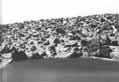
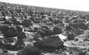
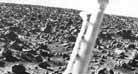
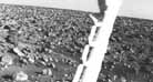
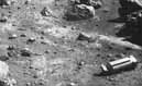
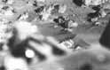
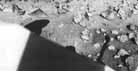
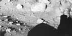
The shadows in figures 98 and 99 are noteworthy. When the cameras are not in use they are stowed with their transparent windows positioned behind protective posts. The placement of these posts was a matter of great debate. Since they obscure about 20° in azimuth of the field of view it was decided to put them where a minimum of the natural scene would be affected. The optimal position was looking toward the opposite camera. The consequence, of course, is inability to take a picture of one camera with the other. During the months prior to launch, when we suspected we might have trouble with the camera azimuth drive, we wondered whether it might not have been an error to deny ourselves a potentially instructive picture of a malfunctioning camera.

Figures 98 and 99 are the closest we can come to a self portrait. Figure 98, taken with camera 1, shows the tip of the shadow of camera 2, situated between the shadows of the S band antenna and the meteorology boom. Figure 99, taken with camera 2, shows the shadow of camera 1 at the upper right. The shadow of the surface sampler is in the center.